Series And Parallel Wiring Diagram Homemadeist

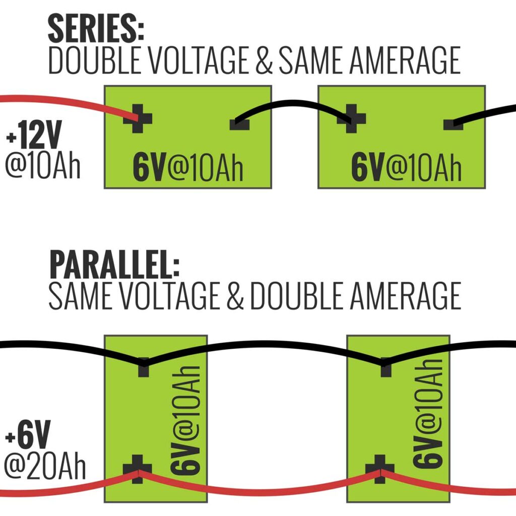
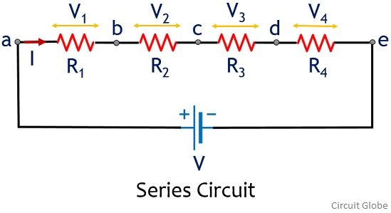
Series And Parallel Wiring Diagram Homemadeist In conclusion, parallel and series wiring diagrams have distinct differences that can greatly impact the performance of your electrical system. understanding the differences between these two types of wiring can help you make informed decisions when it comes to your home or business. whether you choose parallel or series wiring, it is important. Wiring in series and parallel diagram is an important concept in electrical engineering and is used to connect multiple components or devices in a circuit. understanding this concept is essential for designing and analyzing complex electrical systems. when components are wired in series, they are connected end to end, creating a single path for.

Series And Parallel Wiring Diagram Homemadeist In conclusion, a series parallel wiring diagram is a valuable tool for designing and implementing electrical circuits. by carefully following the diagram and considering the voltage, current, and power requirements, it is possible to create a safe and efficient electrical system. whether it is for a simple household appliance or a complex. A series wiring diagram shows how each component of the circuit is connected in a sequence, while a parallel wiring diagram shows how each component of the circuit is connected in parallel. both diagrams are useful in their own way, but for different purposes. a series wiring diagram is typically used to demonstrate how components are connected. In this lesson we go through how to wire a series and parallel circuit and start to understand what voltage will be at each load depending on which you use.i. It is easier to wire a series circuit than a parallel circuit. the incoming cable is attached directly to the device (like a receptacle), and the outgoing cable is also directly attached. a parallel circuit requires you to pigtail wires and to add wire nuts. so, electrical project costs are slightly less when wiring a series circuit.

Series And Parallel Wiring Diagram Homemadeist In this lesson we go through how to wire a series and parallel circuit and start to understand what voltage will be at each load depending on which you use.i. It is easier to wire a series circuit than a parallel circuit. the incoming cable is attached directly to the device (like a receptacle), and the outgoing cable is also directly attached. a parallel circuit requires you to pigtail wires and to add wire nuts. so, electrical project costs are slightly less when wiring a series circuit. When deciding between series and parallel wiring, it is crucial to consider the specific requirements of your electrical system. if reliability and redundancy are important, parallel wiring may be the better choice. however, if simplicity and cost effectiveness are paramount, series wiring might be the way to go. Because we connected three identical speakers in a series parallel combination with our amplifier, zspk1 sees the equivalent power of just one speaker connected to our amp, while zspk2 and zspk3 each see ¼ of the power of a single speaker connection. in the vs lspk1 mesh we have the equivalent of the single driver circuit seen in schematic 3.
Series And Parallel Wiring Diagram Homemadeist When deciding between series and parallel wiring, it is crucial to consider the specific requirements of your electrical system. if reliability and redundancy are important, parallel wiring may be the better choice. however, if simplicity and cost effectiveness are paramount, series wiring might be the way to go. Because we connected three identical speakers in a series parallel combination with our amplifier, zspk1 sees the equivalent power of just one speaker connected to our amp, while zspk2 and zspk3 each see ¼ of the power of a single speaker connection. in the vs lspk1 mesh we have the equivalent of the single driver circuit seen in schematic 3.

Series And Parallel Wiring Diagram Homemadeist

Comments are closed.