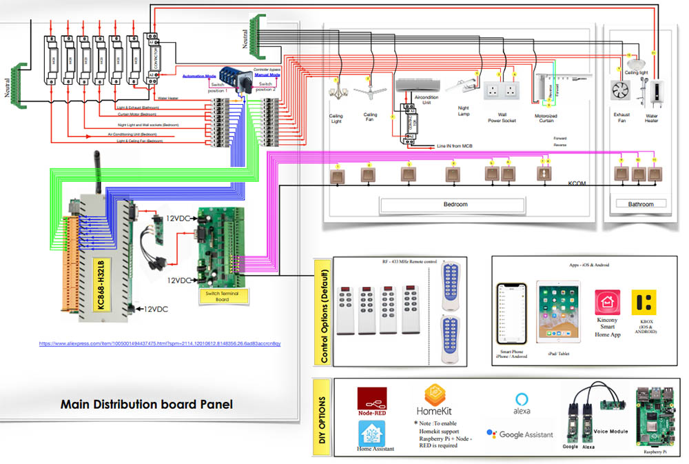
Smart Home Automation Circuit Diagram Wiring View And Schematics Di

Smart Home Automation Circuit Diagram Wiring View And S Make the connection for home automation project as given in the circuit diagram. first of all, we connect the bulb with ac powered sources and with relays as given in the circuit diagram. then the relays are given dc power from the arduino uno board. data pins of the relays are connected at pins 8, 9, 10 and 11 to the arduino which are the. Key components in home automation wiring schematics. home automation wiring schematics typically include the following key components: 1. control center or hubthis is the central processing unit of your smart home system. it receives commands from your devices and sends instructions to other connected components.

Smart Home Automation Project System Wiring Diagram For Beginner Guide Below is a list of some home automation projects which are based on various microcontrollers, arduino, raspberry pi, etc. these home automation projects are covered with detailed explanation of circuit diagrams, source codes and videos. february 14, 2024. Use a cable cutter or sharp scissors to cut the cable cleanly. next, use a wire stripper to remove approximately 1 inch of the outer insulation, revealing the four twisted pairs of wires inside. terminate the cable: terminate the cable by attaching an rj 45 connector to each end. A smart home wiring diagram typically includes power wiring, data cables (like cat6 or cat5e), connections to smart switches, the central smart home panel, and dedicated circuits for heavy duty smart appliances. it’s a blueprint for where components and devices connect within the home’s electrical and data network. 2. 1. photograph your existing wiring and take note of which wires correspond to which zones. 2. unplug the existing controller and remove the wiring from it. 3. put the wiring through the controller and mount it on the wall, drilling holes into the wall and placing drywall anchors if needed. 4.

Comments are closed.