Solid State Cooling Diagrams

2017 2018 Solid State Refrigeration Energy Star Solid state cooling works by employing thin membranes, which vibrate at ultrasonic frequencies when under an electric charge, to move air and dissipate heat. compared to passive cooling, solid state cooling can dissipate more heat while taking less space and being virtually inaudible. compared to air cooling, solid state cooling offers the same. One component phase diagram. figure 1 illustrates the temperatures and pressures at which water can exist as a solid, liquid or vapor. the curves represent the points at which two of the phases coexist in equilibrium. at the point tt vapor, liquid and solid coexist in equilibrium. in the fields of the diagram (phase fields) only one phase exists.

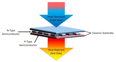
Thermal Management A Broad Overview Of Cooling Techniques 12.5: interpretation of cooling curves. the melting temperature of any pure material (a one component system) at constant pressure is a single unique temperature. the liquid and solid phases exist together in equilibrium only at this temperature. when cooled, the temperature of the molten material will steadily decrease until the melting point. Equilibrium (very slow) cooling ¾solidification in the solid liquid phase occurs gradually upon cooling from the liquidus line. ¾the composition of the solid and the liquid change gradually during cooling (as can be determined by the tie line method.) ¾nuclei of the solid phase form and they grow to consume all the liquid at the solidus line. Thermoelectric cooling uses the peltier effect to create a heat flux at the junction of two different types of materials. a peltier cooler, heater, or thermoelectric heat pump is a solid state active heat pump which transfers heat from one side of the device to the other, with consumption of electrical energy, depending on the direction of the current. A schematic diagram of the cooling device. stage 1: one end of sample is fixed on the body case (u1), and the other is fixed to the revolving disc (m). stage 2: m rotates counterclockwise causing.

First Solid State Cooling Below 100k Thermoelectric cooling uses the peltier effect to create a heat flux at the junction of two different types of materials. a peltier cooler, heater, or thermoelectric heat pump is a solid state active heat pump which transfers heat from one side of the device to the other, with consumption of electrical energy, depending on the direction of the current. A schematic diagram of the cooling device. stage 1: one end of sample is fixed on the body case (u1), and the other is fixed to the revolving disc (m). stage 2: m rotates counterclockwise causing. Determining the state of water using the phase diagram for water given in figure 10.31, determine the state of water at the following temperatures and pressures: (a) −10 °c and 50 kpa (b) 25 °c and 90 kpa (c) 50 °c and 40 kpa (d) 80 °c and 5 kpa (e) −10 °c and 0.3 kpa (f) 50 °c and 0.3 kpa. solution. One component systems (1) the composition is fixed at c = 1 and the independent variables are t and p. f = c – p 2 <=> f p = 3. the system is bivariant (f = 2) if one phase is present, univariant (f = 1) if two are present and invariant (f = 0) if three are present. in the schematic example below, the possible phases are two solid state.

Our Technology Solid State Cooling Systems Determining the state of water using the phase diagram for water given in figure 10.31, determine the state of water at the following temperatures and pressures: (a) −10 °c and 50 kpa (b) 25 °c and 90 kpa (c) 50 °c and 40 kpa (d) 80 °c and 5 kpa (e) −10 °c and 0.3 kpa (f) 50 °c and 0.3 kpa. solution. One component systems (1) the composition is fixed at c = 1 and the independent variables are t and p. f = c – p 2 <=> f p = 3. the system is bivariant (f = 2) if one phase is present, univariant (f = 1) if two are present and invariant (f = 0) if three are present. in the schematic example below, the possible phases are two solid state.

Solid State Technology Thermoelectric Cooling Heating

Comments are closed.