Solved 4 28 For Each Of The Following E R Diagrams From Chegg

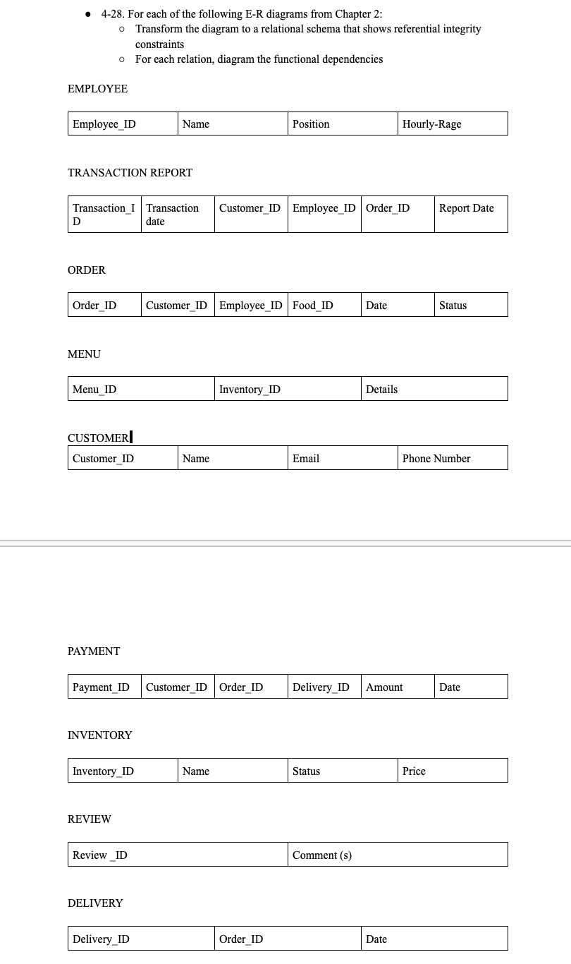
Solved 4 28 For Each Of The Following E R Diagrams From Chegg Engineering; computer science; computer science questions and answers; 4 28. for each of the following e r diagrams from chapter 2: transform the diagram to a relational schema that shows referential integrity constraints for each relation, diagram the functional dependencies. Figure 4 5. 4 28. for each of the following e r diagrams from chapter 2: i. transform the diagram to a relational schema that shows referential integrity constraints (see figure 4 5 for an example of such a schema). figure 4 5. there are 4 steps to solve this one.

Solved 4 28 п їfor Each Of The Following E R Diagrams From Chegg Draw an erd for the following description: each department has a unique name, a unique number, and a particular employee who manages the department. we keep track of the start date when that employee began managing the department. a department may have several locations. february 11, 2018 entity relationship (er) diagrams 13. After designing the er diagram of system, we need to convert it to relational models which can directly be implemented by any rdbms like oracle, mysql etc. in this article we will discuss how to convert er diagram to relational model for different scenarios. case 1: binary relationship with 1:1 cardinality with total participation of an entity. Er diagram stands for entity relationship diagram, also known as erd is a diagram that displays the relationship of entity sets stored in a database. in other words, er diagrams help to explain the logical structure of databases. er diagrams are created based on three basic concepts: entities, attributes and relationships. • for multivalued attribute m in entity set e – create a relation schema r to store m, with attribute a corresponding to m • a is single valued version of m – attributes of r are: a (primary key(e) – primary key of r includes all attributes of r • each value in m for entity e must be unique – foreign key constraint from r to e, on.

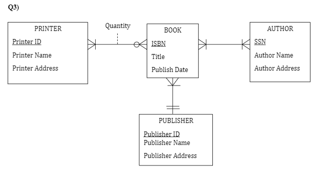
Solved For Each Of The Following E R Diagrams Transform The C Er diagram stands for entity relationship diagram, also known as erd is a diagram that displays the relationship of entity sets stored in a database. in other words, er diagrams help to explain the logical structure of databases. er diagrams are created based on three basic concepts: entities, attributes and relationships. • for multivalued attribute m in entity set e – create a relation schema r to store m, with attribute a corresponding to m • a is single valued version of m – attributes of r are: a (primary key(e) – primary key of r includes all attributes of r • each value in m for entity e must be unique – foreign key constraint from r to e, on. For the following reaction at a particular temperature which takes place as follows $2 \mathrm{~n} {2} \mathrm{o} {5} \rightarrow 4 \mathrm{no} {2} \… video solution, solved step by step from our expert human educators: for each of the following reaction diagrams, estimate the activation energy. New jersey, us mostly asked from. for each of the following e r diagrams from chapter 2: i. transform the diagram to a relational schema that shows referential integrity constraints (see figure 4 5 for an example of such a schema): ii. for each relation, diagram the functional dependencies (see figure 4 23 for an example).

Solved For Each Of The Following E R Diagrams Transform The C For the following reaction at a particular temperature which takes place as follows $2 \mathrm{~n} {2} \mathrm{o} {5} \rightarrow 4 \mathrm{no} {2} \… video solution, solved step by step from our expert human educators: for each of the following reaction diagrams, estimate the activation energy. New jersey, us mostly asked from. for each of the following e r diagrams from chapter 2: i. transform the diagram to a relational schema that shows referential integrity constraints (see figure 4 5 for an example of such a schema): ii. for each relation, diagram the functional dependencies (see figure 4 23 for an example).

Comments are closed.