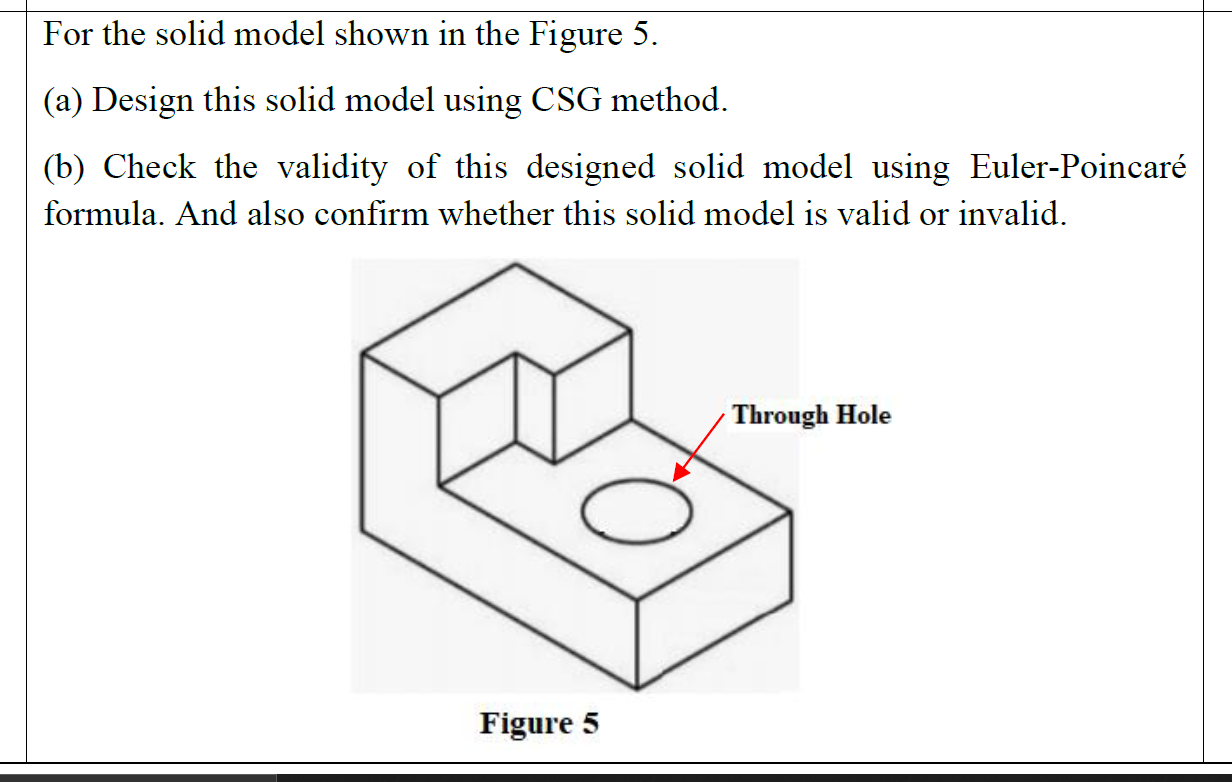
Solved For The Solid Model Shown In The Figure 5 A Design Chegg

Solved For The Solid Model Shown In The Figure 5 A Design Chegg Step 1. vi. create solid model and multiview drawing. create a solid model of the object shown below in fig 5.143. fully define all sketches and ensure dimensions shown are correct. use this solid model to then construct the multiview drawing using the drawing feature in solidworks. 01.00 05 0 275 2.05 figure 5.143 adjustable guide. • the device from a copying machine is shown. it moves in a horizontal plane. develop the dynamic model, assuming that mass of bar is negligible compared to attached mass m 2 and angular motions are small. the mass is subjected to a step input f, find an expression for the displacement of point b after the transient motions have died out. 30.

Solved Q4 Create The Solid Model Shown In The Figure Below Chegg Csg operations. here each of the leaf nodes is a valid solid primitive. the intermediate nodes are the transition states of the solid modeling (r set) operations. the root node is the resulting solid from the set operations. here n primitives require (n 1) boolean operations to complete the construction of the object. the tree will have (2n 1. The input dataset, which can be written manually or developed graphically in velvet, employs parsing techniques to simplify what can be a very tedious and error prone step in finite element analysis. the dataset for this 6 element truss is: problem description. nodes=5 elements=6. nodes. 1 x=0 y=100 z=0 constraint=pin. Consider the pin jointed cantilever truss shown in figure 1. t s p q r p l l l figure 1: cantilever truss (a) determine the forces all of the members of the truss due to the applied load p, distinguishing between tension and compression. solution: we may use the method of joints to solve for the forces in the mem bers of the truss. Figure 9: the maxwell model. the "maxwell" solid shown in figure 9 is a mechanical model in which a hookean spring and a newtonian dashpot are connected in series. the spring should be visualized as representing the elastic or energetic component of the response, while the dashpot represents the conformational or entropic component.

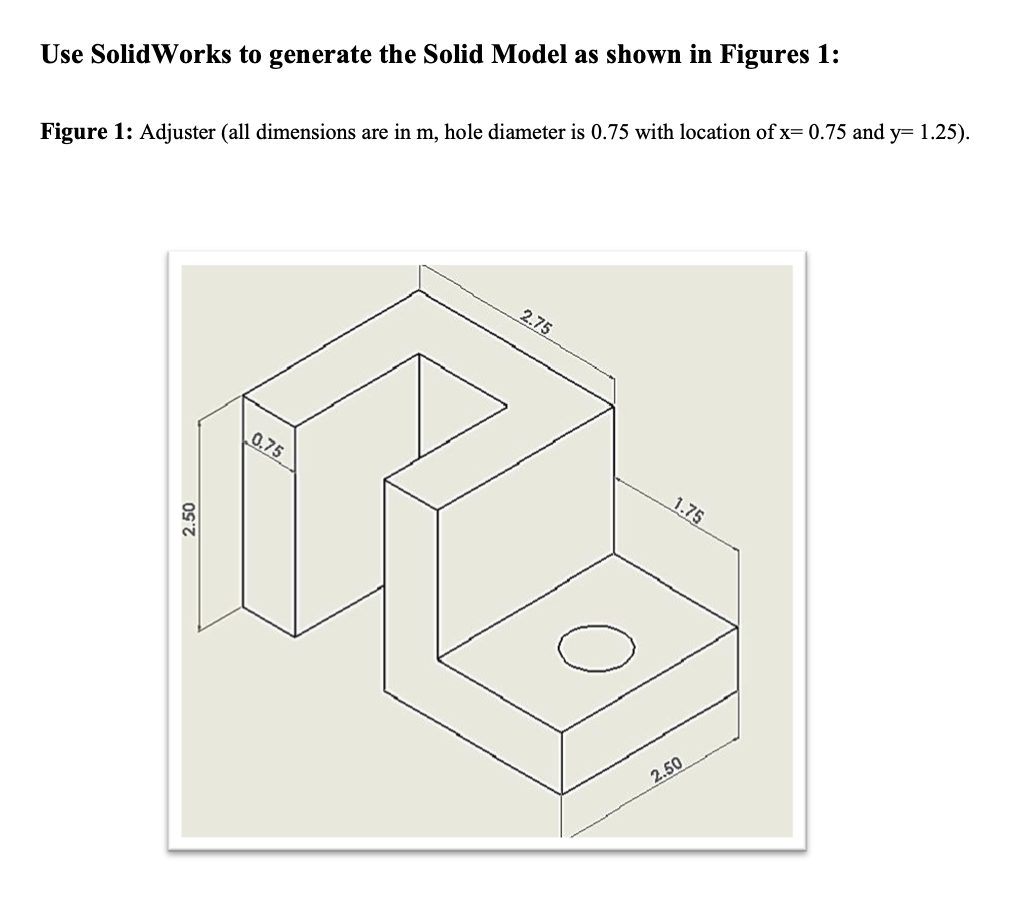
Solved Use Solidworks To Generate The Solid Model As Shown Chegg Consider the pin jointed cantilever truss shown in figure 1. t s p q r p l l l figure 1: cantilever truss (a) determine the forces all of the members of the truss due to the applied load p, distinguishing between tension and compression. solution: we may use the method of joints to solve for the forces in the mem bers of the truss. Figure 9: the maxwell model. the "maxwell" solid shown in figure 9 is a mechanical model in which a hookean spring and a newtonian dashpot are connected in series. the spring should be visualized as representing the elastic or energetic component of the response, while the dashpot represents the conformational or entropic component. The objective of this chapter is to figure out the forces being carried by these structures so that as an engineer, you can decide whether the structure can sustain these forces or not. note: this includes "reaction" forces from the supports as well. external forces: "loads" acting on your structure. of the structure together. Microsoft word hw1.docx. 1. solve problem 1.3 3(c) 2. solve problem 2.2 2(b) a two–dimensional truss shown in the figure is made of aluminum with young’s modulus e = 80 gpa and failure stress σy = 150 mpa. determine the minimum cross sectional area of each member so that the truss is safe with safety factor 1.5. 60 kn.

Solved Create A Solid Model Of The Part Shown In The Figure Cheggођ The objective of this chapter is to figure out the forces being carried by these structures so that as an engineer, you can decide whether the structure can sustain these forces or not. note: this includes "reaction" forces from the supports as well. external forces: "loads" acting on your structure. of the structure together. Microsoft word hw1.docx. 1. solve problem 1.3 3(c) 2. solve problem 2.2 2(b) a two–dimensional truss shown in the figure is made of aluminum with young’s modulus e = 80 gpa and failure stress σy = 150 mpa. determine the minimum cross sectional area of each member so that the truss is safe with safety factor 1.5. 60 kn.

Comments are closed.