T S Diagram For Air

T S рґрёр рісђр рјрјр рірѕр рґсѓс р 90 с рѕс рѕ The t s diagram is one of the most used plots in thermodynamics. it is used to analyze vapor power cycles, gas power cycles, and gas refrigeration cycles along with the p v diagram. hence it becomes really important to understand the t s diagram. once you understand it, applied thermodynamics becomes easier to interpret and analyze. Online interactive p h and t s diagram. please allow more processing time for mixed refrigerant. submit all changes below. click on diagram for properties. or input data for properties. pressure, bar. enthalpy, kj kg. quantity. value.

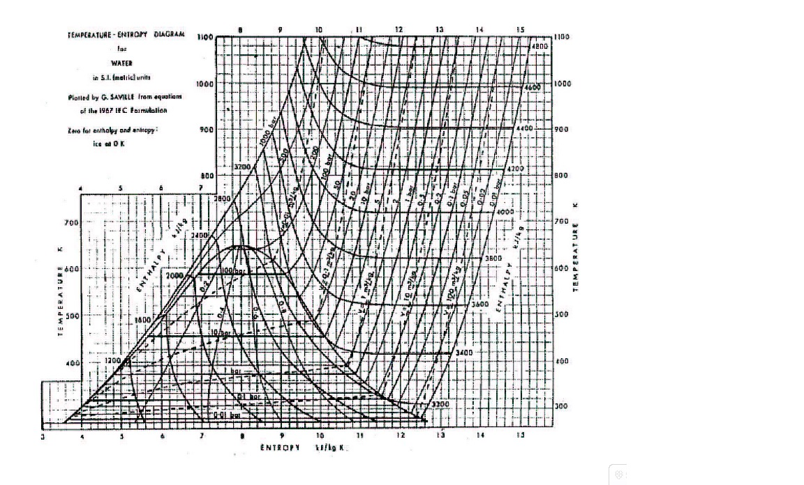
Ts Diagram Of Air Pdf V. t. e. in thermodynamics, a temperature–entropy (t–s) diagram is a thermodynamic diagram used to visualize changes to temperature (t ) and specific entropy (s) during a thermodynamic process or cycle as the graph of a curve. it is a useful and common tool, particularly because it helps to visualize the heat transfer during a process. Temperature entropy (t s) diagram. figure 1 t s diagram for water. in the liquid vapor region in figure 1, water and steam exist together. for example, at point a, water with an entropy (s f) given by point b, exists together with steam with an entropy (s g) given by point c. the quality of the mixture at any point in the liquid vapor region. As described on the work slide, the area under a process curve on a p v diagram is equal to the work performed by a gas during the process. on the right of the figure we have plotted the temperature versus the entropy of the gas. this plot is called a t s diagram. lines of constant pressure curve from the lower left to upper right on a t s diagram. Appendix 2: diagrams t s. figure a1: figure a2: figure a3: figure a4: t s diagram for water t s diagram for ammonia t s diagram for r 134a t s diagram for air. note: the above listed graphs are prepared by utilizing the engineering equation software (ees) available at ontario tech. university (formerly university of ontario institute of.

Air T S Diagram As described on the work slide, the area under a process curve on a p v diagram is equal to the work performed by a gas during the process. on the right of the figure we have plotted the temperature versus the entropy of the gas. this plot is called a t s diagram. lines of constant pressure curve from the lower left to upper right on a t s diagram. Appendix 2: diagrams t s. figure a1: figure a2: figure a3: figure a4: t s diagram for water t s diagram for ammonia t s diagram for r 134a t s diagram for air. note: the above listed graphs are prepared by utilizing the engineering equation software (ees) available at ontario tech. university (formerly university of ontario institute of. Thermodynamics. thermodynamic diagrams are diagrams used to represent the thermodynamic states of a material (typically fluid) and the consequences of manipulating this material. for instance, a temperature– entropy diagram (t–s diagram) may be used to demonstrate the behavior of a fluid as it is changed by a compressor. A temperature entropy diagram (t s diagram) is the type of diagram most frequently used to analyze energy transfer system cycles. it is used in thermodynamics to visualize changes to temperature and specific entropy during a thermodynamic process or cycle. this is because the work done by or on the system and the heat added to or removed from.

Diagram Air T S Diagram Mydiagram Online Thermodynamics. thermodynamic diagrams are diagrams used to represent the thermodynamic states of a material (typically fluid) and the consequences of manipulating this material. for instance, a temperature– entropy diagram (t–s diagram) may be used to demonstrate the behavior of a fluid as it is changed by a compressor. A temperature entropy diagram (t s diagram) is the type of diagram most frequently used to analyze energy transfer system cycles. it is used in thermodynamics to visualize changes to temperature and specific entropy during a thermodynamic process or cycle. this is because the work done by or on the system and the heat added to or removed from.

Comments are closed.