Technical Drawings Third Angle Projection General Dimensioning And

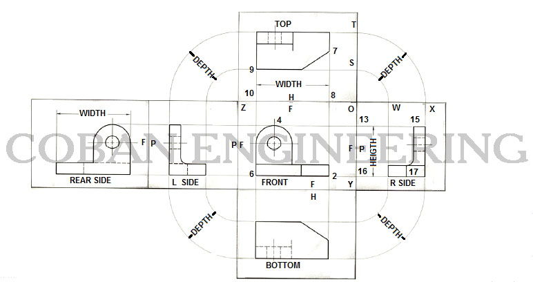
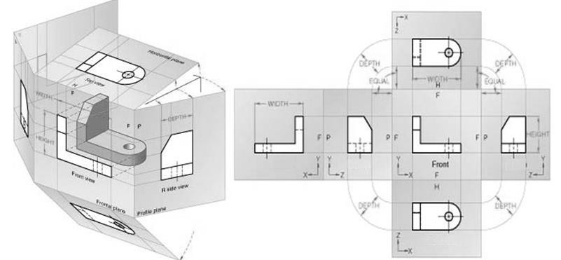
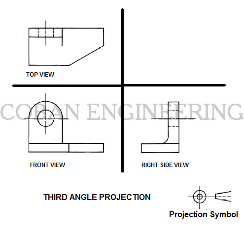
Technical Drawings Third Angle Projection General Dimensioning And First vs third angle – orthographic views. by gd&t basics on march 30, 2021. orthographic views allow us to represent a 3d object in 2d on a drawing. orthographic views can show us an object viewed from each direction. how the views are laid out on a drawing depends on whether 3 rd angle or 1 st angle projection is being used. So far we have only looked at third angle projection, since this is used here. figure 3.1.7 shows a part in third angle projection, figure 3.1.8 shows the same part in first angle projection. to avoid confusion, drawings must be identified by means of the symbols shown in figure 3.1.9 as either first angle or third angle projection drawings.

Technical Drawings Third Angle Projection General 50 Off Download now. the first angle and third angle projection system are common terms that you must have seen in technical drawings. these projection systems are used to represent the features and dimensions of a 3d orthographic drawing on a 2d plane. in this article, we will learn all about first angle and third angle projection systems. 2. multiview layout and orientation. a single orthographic projection almost never provides enough information to fully describe a component. this is because all of the information about dimensions parallel to the viewing direction are lost completely. a multiview drawing combines several orthographic projections into a single document, often. Projections and views. a three dimensional object can be represented in a single plane, such as on a sheet of paper, using projecting lines and planes. all projection theory is based on two variables: line of sigh t (projecting lines) and plane of projection. a line of sight (los) is an imaginary line between an observer’s eye and an object. Apter 4 orthographic projection and multiview construc. ionsunderstand the basic orthographic projection pri. ciples. be able to perform 1st and 3rd angle ♦ projection. .using the construction line command ♦ in autoca. to draw.using the autocad running object snaps ♦. use autocad’s ♦ autosnap and autotrack features.

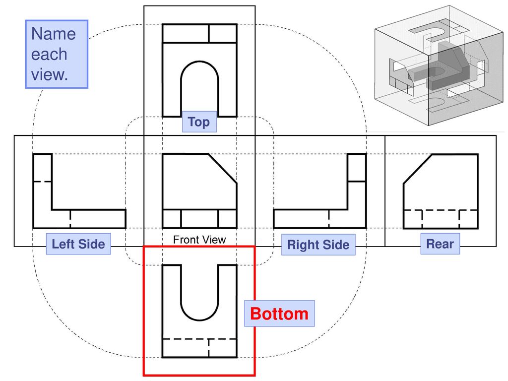
Technical Drawings Third Angle Projection General 52 Off Projections and views. a three dimensional object can be represented in a single plane, such as on a sheet of paper, using projecting lines and planes. all projection theory is based on two variables: line of sigh t (projecting lines) and plane of projection. a line of sight (los) is an imaginary line between an observer’s eye and an object. Apter 4 orthographic projection and multiview construc. ionsunderstand the basic orthographic projection pri. ciples. be able to perform 1st and 3rd angle ♦ projection. .using the construction line command ♦ in autoca. to draw.using the autocad running object snaps ♦. use autocad’s ♦ autosnap and autotrack features. Third angle projection is similar, however the projection direction is the opposite to first angle projection. third angle projection. to get from the view on the left to the view on the right, we rotate the front of the model to the left and the rear of the model to the right. similarly, the opposite is also true – to get from the view on. Third angle projection is primarily used in the united states and canada, where it is the default projection system according to asme standard asme y14.3 2003 and british standard bs 8888.when the 3d object is projected into 2d "paper" after projected front view the top view is placed on the top and the left view is placed on the left.

Technical Drawings Third Angle Projection General 52 Off Third angle projection is similar, however the projection direction is the opposite to first angle projection. third angle projection. to get from the view on the left to the view on the right, we rotate the front of the model to the left and the rear of the model to the right. similarly, the opposite is also true – to get from the view on. Third angle projection is primarily used in the united states and canada, where it is the default projection system according to asme standard asme y14.3 2003 and british standard bs 8888.when the 3d object is projected into 2d "paper" after projected front view the top view is placed on the top and the left view is placed on the left.

Technical Drawings Third Angle Projection General Dimensioning And

Comments are closed.