Thermostat Characteristic Diagram Cooling Mechanical

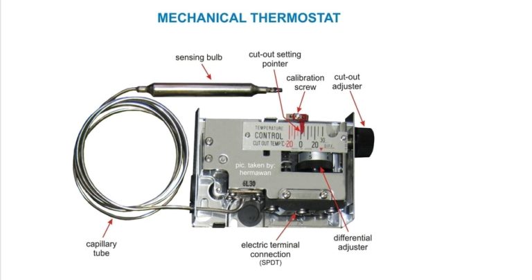
Ppt Cooling System Theory Powerpoint Presentation Free Download Id The mechanical thermostat is a simple but effective device used to control the temperature in a heating or cooling system. it consists of a temperature sensor, a control switch, and a mercury filled bulb or bimetallic strip. when the temperature in the room reaches the desired level, the thermostat activates the switch, turning off the heating. R or rc wire (power) connected to the r power terminal to power the thermostat. w wire (heat), connected to the heating control. g wire (fan) connected to the fan control to operate a blower in your hvac system. y1 wire (cooling) connected to the y terminal compressor refrigerant system.

How Does A Mechanical Thermostat Work The Home Hacks Diy The hvac wiring diagram thermostat illustrates the electrical connections between the thermostat, the heating or cooling system, and the power supply. it shows the different wires and terminals involved in the system and their corresponding functions. the diagram provides a visual representation of how the thermostat interacts with the hvac. Unscrew the two wires from the terminals. remove the motherboard of the old 2 wire thermostat and put the new 2 wire thermostat in its place. reconnect the red and white wire, tighten down the set screw, and put the control panel back on. test the 2 wire thermostat wiring by turning the furnace on. If you have a c wire, place it into the c terminal on your wall plate. c wire adapters are available here. let’s look at the g wire. this wire goes to the g terminal on your new thermostat. of the y, y1, and y2 wires, y or y1 go to the y terminal and y2 to the y2 terminal. the o b wire can have many configurations. Air conditioner thermostat wiring details and color code. r terminal is connected to the red wire or r wire this is 24 volt power for the thermostat and controlled devices. origin is the control transformer and then the r terminal. g terminal is connected to the green wire or g wire this is for the blower fan in the air handler.

Sketch Of Thermoelectric Cooling System For The Thermostat Download If you have a c wire, place it into the c terminal on your wall plate. c wire adapters are available here. let’s look at the g wire. this wire goes to the g terminal on your new thermostat. of the y, y1, and y2 wires, y or y1 go to the y terminal and y2 to the y2 terminal. the o b wire can have many configurations. Air conditioner thermostat wiring details and color code. r terminal is connected to the red wire or r wire this is 24 volt power for the thermostat and controlled devices. origin is the control transformer and then the r terminal. g terminal is connected to the green wire or g wire this is for the blower fan in the air handler. 0:00. 2:15. thermostats are what we refer to as “temperature actuated switches,” meaning they will automatically open or close their electrical contacts upon a change in ambient temperature. this means that we can set the thermostat in the room to a comfortable level and allow the heating or cooling system regulate the temperature. Mount the new thermostat base: install the base plate of the emerson thermostat onto the wall. you may need screws and a screwdriver. use the built in level to level it up. connect the wires: please see the wiring diagrams in fig 2 5 connect each wire to its corresponding terminal as in the image below: fig 1.

Comments are closed.