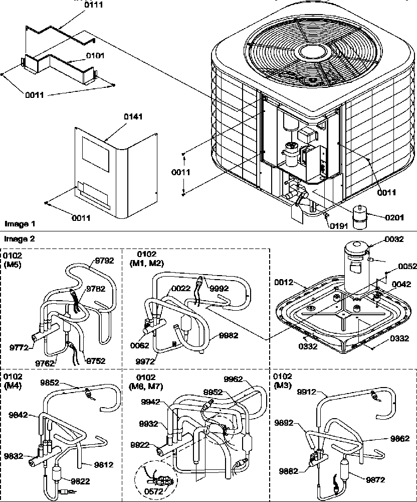
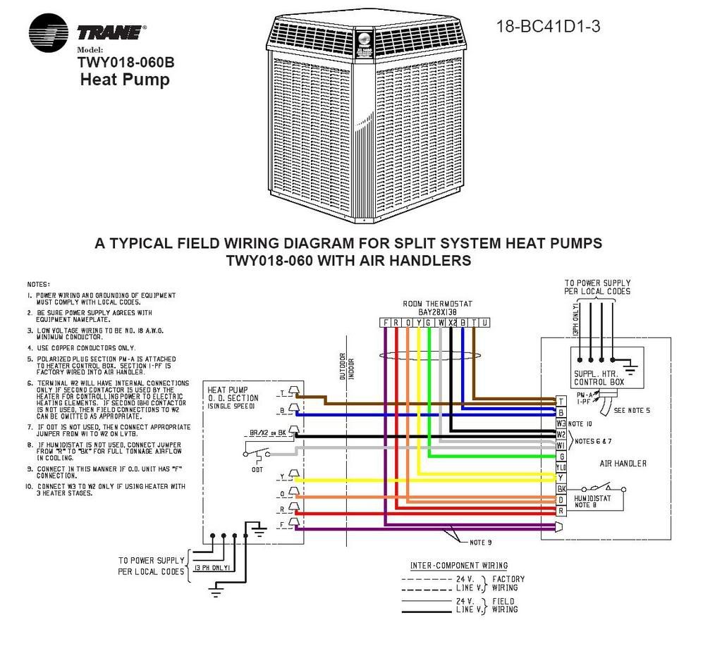
Trane Air Conditioner Diagram

Trane Air Conditioner Parts Diagram Wiring Diagram Step 2 remove the pressure tap cap and valve cores from both service valves. step 3 purge the refrigerant lines and indoor coil with dry nitrogen. step 4 wrap a wet rag around the valve body to avoid heat damage and continue the dry nitro gen purge. braze the refrigerant lines to the service valves. The tem6 series air handler is designed for installation in a closet, utility room, alcove, basement, crawlspace or attic. these versatile units are applicable to air conditioning and heat pump applications. several models are available to meet the specific requirements of the outdoor equipment.

Trane Central Air Conditioner Model Btb730a100a1 Wiring Diagram Page 1: table of contents. 18 ac79d1 10e en installation and operation manual condensing units 4ttr3 all phases of this installation must comply with national, state and local codes important – this document is customer property and is to remain with this unit. please return to service informa tion pack upon completion of work. Trane link or comfortlink ™ ii variable speed heat pumps and air conditioners 4twv8x24a1000a 4twv8x36a1000a 4twv8x48a1000a 4twv8x60a1000a 4ttv8x24a1000a 4ttv8x36a1000a 4ttv8x48a1000a 4ttv8x60a1000a tm the diagnostics mobile app is available by scanning a qr code located inside this unit or by searching for the link diagnostics app in your app. Disconnect all electric power to the indoor air handler or furnace before removing access panels to perform any maintenance. disconnect power to both the indoor and outdoor units. a clean filter saves money. help ensure top efficiency by cleaning the filter regularly. when the unit circulates and filters the air in your home, dust. Shown in figure 2 (see page 2). 2. the unit should be set on a level support pad at least as. large as the unit base pan, such as a concrete slab. if this. is not the application used please refer to application. bulletin "trane apb2001 02". 3. the support pad must not be in direct contact with any.

Trane Central Air Conditioner Model Btb730a100a1 Wiring Diagram Disconnect all electric power to the indoor air handler or furnace before removing access panels to perform any maintenance. disconnect power to both the indoor and outdoor units. a clean filter saves money. help ensure top efficiency by cleaning the filter regularly. when the unit circulates and filters the air in your home, dust. Shown in figure 2 (see page 2). 2. the unit should be set on a level support pad at least as. large as the unit base pan, such as a concrete slab. if this. is not the application used please refer to application. bulletin "trane apb2001 02". 3. the support pad must not be in direct contact with any. This manual is also suitable for: view and download trane xr 13 product data online. split system cooling. xr 13 air conditioner pdf manual download. also for: 4ttr3018 060. Air conditioning product may result in personal injury and or property damage. the manufacture or seller cannot be responsible for the interpretation of this information, nor can it assume any liability in connec tion with its use. these units use r 410a refrigerant which operates at 50 to 70% higher pressures than r 22. use only.

Comments are closed.