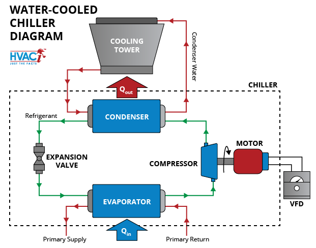
Water Chiller System Diagram

How A Water Chiller Works At Karen Warden Blog A chiller is made up of the 4 major components required for the refrigeration process which are: a) compressor, b) condenser, c) evaporator and d) expansion valve. to produce chilled water, the refrigerant absorbs heat from the water and thus, chilling the water to about 6.7°c (44°f). 1) 4000 ton water cooled centrifugal chiller. a standard chilled water system diagram consists of the chiller, cooling tower and pump. the chilled water distribution to ahus and fcus is usually included unless the system is large until a separate diagram is needed.

Schematic Of A Typical Chilled Water System Download Scientific Diagram Learn how to read chilled and condenser water schematics, identify the main components and symbols, and see real world examples. find out the purpose and design types of chillers, pumps, valves, risers, ahu's and cooling towers. Learn how a water chiller system works by cooling water using refrigeration technology and transferring heat to the environment. see a visual breakdown of the main components, such as the chiller unit, pump, heat exchanger, and control panel. The chilled water schematic diagram is a visual representation of the components and flow of a chilled water system. it provides an overview of how the system works and allows engineers and technicians to understand how the different parts of the system are connected and interact with each other. the schematic diagram typically starts with a. Sure setpoint or chilled water setpoint.select chiller for 2 to 4°f lower supply chilled water temperature than the cooling coils, to allow supply temperature reduction compensation for. irside low Δt or increased system load.install pressure independent cooling coil control valves to preserve system.

The Basics Of Chillers Hvac Investigators The chilled water schematic diagram is a visual representation of the components and flow of a chilled water system. it provides an overview of how the system works and allows engineers and technicians to understand how the different parts of the system are connected and interact with each other. the schematic diagram typically starts with a. Sure setpoint or chilled water setpoint.select chiller for 2 to 4°f lower supply chilled water temperature than the cooling coils, to allow supply temperature reduction compensation for. irside low Δt or increased system load.install pressure independent cooling coil control valves to preserve system. A basic chilled water system diagram is a representation of the components and flow of a typical chilled water system. chilled water systems are commonly used in commercial and industrial buildings to provide cooling for air conditioning, process cooling, and other applications. the diagram typically includes several key components, such as the. The piping diagram, also known as a schematic or flow diagram, outlines the path that the chilled water follows as it travels through the chiller system. it indicates the location and size of pipes, valves, pumps, and other components, providing a visual representation of the system’s layout. by analyzing the piping diagram, technicians can.

Comments are closed.