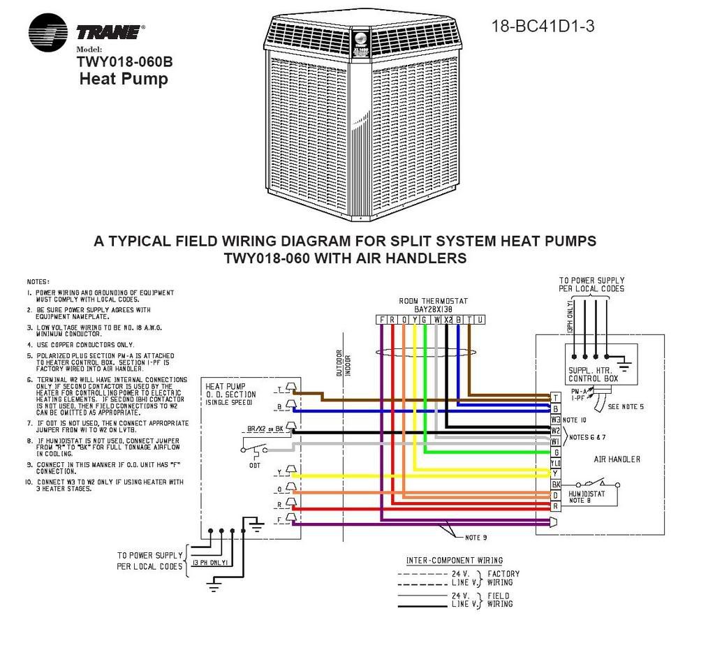
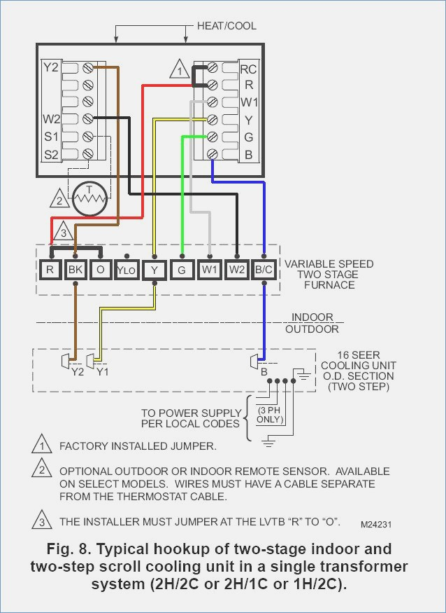
Wiring Diagram For Trane Air Conditioner Wiring Diagram

Trane Central Air Conditioner Model Btb730a100a1 Wiring Diagram ©2016 trane 18 gf74d1 1f en safety section air handlers important: this document contains a wiring diagram, a parts list, and service information. this is customer property and is to remain with this unit. please return to service information pack upon completion of work. important: these instructions do not cover all. ©2022 trane 18 bc106d1 1d en safety section important — this document contains a wiring diagram and service information. this is customer property and is to remain with this unit. please return to service information pack upon completion of work. warning hazardous voltage! failure to follow this warning could result in.

Trane Air Conditioner Wiring Diagram The wiring diagram will show the connections between these components and any other related elements, such as control panels, sensors, and switches. trane air conditioner wiring diagrams are typically divided into two distinct parts. the first part outlines the connections between the various components and the second part outlines the. Step 2 remove the pressure tap cap and valve cores from both service valves. step 3 purge the refrigerant lines and indoor coil with dry nitrogen. step 4 wrap a wet rag around the valve body to avoid heat damage and continue the dry nitro gen purge. braze the refrigerant lines to the service valves. System start up procedures. step 13: allow system to run for a minimum of 10 minutes in the cooling mode. a: for fixed orifice installation: use the superheat charging chart to obtain proper superheat based on indoor outdoor conditions. b: for txv installation: charge the system to 10 degrees of subcooling. The energized compressor contactor (cc) completes the circuit to the compressor for 1st stage (low) operation and the outdoor single speed fan motor (odm). the indoor fan motor (ecm) will operate on low speed. the room thermostat will continue to cycle the compressor and fans to maintain the desired temperature.

Trane Central Air Conditioner Model Btb730a100a1 Wiring Diagram System start up procedures. step 13: allow system to run for a minimum of 10 minutes in the cooling mode. a: for fixed orifice installation: use the superheat charging chart to obtain proper superheat based on indoor outdoor conditions. b: for txv installation: charge the system to 10 degrees of subcooling. The energized compressor contactor (cc) completes the circuit to the compressor for 1st stage (low) operation and the outdoor single speed fan motor (odm). the indoor fan motor (ecm) will operate on low speed. the room thermostat will continue to cycle the compressor and fans to maintain the desired temperature. Environment. trane advocates the responsible handling of all refrigerants inclu ding industry replacements for cfcs such as hcfcs and hfcs. important responsible refrigerant practices trane believes that responsible refrigerant practices are important to the environment, our customers, and the air conditioning industry. all technicians who handle. Rnal surfaces of the tubing using an emery cloth.step 2 remove the pressur. tap cap and valve cores from both service valves.step 3 purge the r. frigerant lines and indoor coil with dry nitrogen.step 4 wrap a wet rag around the valve body to avo. d heat damage and continue the dry nitrogen purge.

Wiring Diagram For Trane Air Conditioner Wiring Diagram Environment. trane advocates the responsible handling of all refrigerants inclu ding industry replacements for cfcs such as hcfcs and hfcs. important responsible refrigerant practices trane believes that responsible refrigerant practices are important to the environment, our customers, and the air conditioning industry. all technicians who handle. Rnal surfaces of the tubing using an emery cloth.step 2 remove the pressur. tap cap and valve cores from both service valves.step 3 purge the r. frigerant lines and indoor coil with dry nitrogen.step 4 wrap a wet rag around the valve body to avo. d heat damage and continue the dry nitrogen purge.

Trane Air Conditioning Wiring Diagram

Comments are closed.