Xylem Goulds Shv Series Installation Operation And Maintenance

Xylem Goulds Shv Series Installation Operation And Maintenance View and download xylem goulds shv series installation, operation and maintenance instructions online. goulds shv series water pump pdf manual download. also for: goulds npv series, npv 1sl, npv 1sr, npv 2sl, npv 2sr, npv 3sl, npv 3sr, 10shv, 9shv, 4shv, 7shv, 5shv. 10. install new casing o ring and casing, torquing cas ing bolts to 50 lbs. in. 11. check reassembled unit for binding. if binding oc curs, realign casing over impeller eye. 12. assembly is complete. shv series disassembly follow all warnings and instructions in the "maintenance" section of this manual. while complete disassembly of the unit.

Xylem Goulds Hms Installation Operation And Maintenance Instructions Regular inspection and maintenance will increase service life. base schedule on operating time. refer to section 8. 2. installation: 2.1. general 2.1.1. locate pump as near liquid source as possible (below level of liquid for automatic operation). 2.1.2. protect from freezing or flooding. 2.1.3. allow adequate space for servicing and. Arrange the connections on the terminal block closed end splices in accordance with the required power supply. connect the mains leads (l1, l2, l3, and ground (earth) ) according to applicable cable chart. the ground (earth) lead must be 50 mm (2.0 in.) longer than the phase conductors in the junction box of the unit. The purpose of this manual is to provide necessary information for: installation. operation. maintenance. caution: read this manual carefully before installing and using the product. improper use of the product can cause personal injury and damage to property, and may void the warranty. notice:. 6.2 maintenance every 4000 hours of operation or every year. when the first of the two limits is reached: measure the pressure at zero flow rate and compare it with the pressure measured during initial start up; if the pressure has decreased by more than 15%, check the condition of impeller, pump body and wear rings.

Xylem Goulds Npe Installation Operation And Maintenance Instructions The purpose of this manual is to provide necessary information for: installation. operation. maintenance. caution: read this manual carefully before installing and using the product. improper use of the product can cause personal injury and damage to property, and may void the warranty. notice:. 6.2 maintenance every 4000 hours of operation or every year. when the first of the two limits is reached: measure the pressure at zero flow rate and compare it with the pressure measured during initial start up; if the pressure has decreased by more than 15%, check the condition of impeller, pump body and wear rings. Page 10: packed box instructions. 3. install the two piece teflon lantern ring supplied as 11. apply loctite #271 or equivalent, to new impeller ® shown in figure 13. note: two pieces make one ring. bolt threads and tighten to: notches on ring must face each other, but alignment " 16 bolts 20 lbs. ft. Connect the t3 and t4 cables from the mixer or the pump to the t3, t4 terminal. create as much separation as possible between the power cores and the control cables. keep the t3 and t4 cables twisted and shielded as close to the terminals as possible. ethernet.

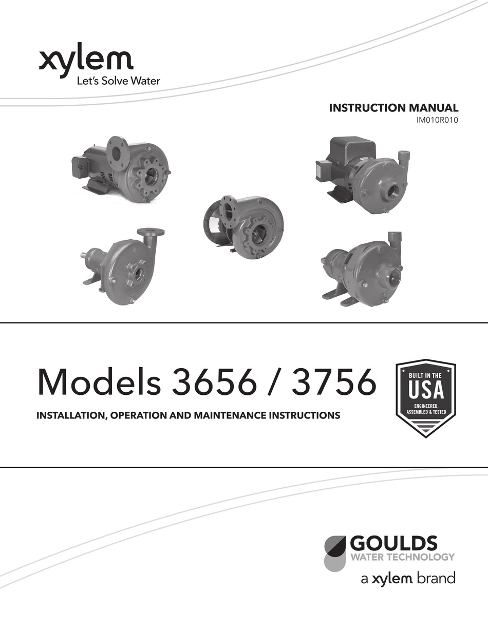
Xylem Goulds 3656 Installation Operation And Maintenance Instructions Page 10: packed box instructions. 3. install the two piece teflon lantern ring supplied as 11. apply loctite #271 or equivalent, to new impeller ® shown in figure 13. note: two pieces make one ring. bolt threads and tighten to: notches on ring must face each other, but alignment " 16 bolts 20 lbs. ft. Connect the t3 and t4 cables from the mixer or the pump to the t3, t4 terminal. create as much separation as possible between the power cores and the control cables. keep the t3 and t4 cables twisted and shielded as close to the terminals as possible. ethernet.

Comments are closed.